Now this analysis is for solid parts and not 3d printed parts so your analysis will probably not be exactly what you will get in real life.
Thursday, December 29, 2016
FEM in FreeCAD
I have made a small instruction video on how to play around with the FEM workbench in FreeCAD as well as how to generate and export files from the OpenBiped/OpenSEA projects.
Now this analysis is for solid parts and not 3d printed parts so your analysis will probably not be exactly what you will get in real life.
Now this analysis is for solid parts and not 3d printed parts so your analysis will probably not be exactly what you will get in real life.
Tuesday, December 27, 2016
SEA Cad files now available!
This is post 3 in the OpenSEA project, if you have missed part one and two see post one for some background.
I started this project with FreeCAD to design the parts, but now i am switching over to OpenSCAD, mainly because of the benefits of SolidPython. I have forked the SolidPython repository and will extend it to fit the needs of the OpenBiped project. One of the big benefits of SolidPython is the ability to auto-generate a Bill Of Materials (BOM) with cost and 3d printing time, i also plan to extend it with weight and filament usage.
Here is an example output: (not a complete SEA, nor real print time or cost for 3d printed parts)
| Desc. | Count | Unit Price | Total Price | Print Time |
| A2212 | 1 | RMB 31.28 | RMB 31.28 | 0 |
| Fibre Glass Rod 4mm | 4 | RMB 2.78 | RMB 11.12 | 0 |
| A2212 Attachment | 1 | RMB 0.20 | RMB 0.20 | 32 |
| ESC 40W | 1 | RMB 31.28 | RMB 31.28 | 0 |
| 3d Printed Spring | 1 | RMB 0.50 | RMB 0.50 | 30 |
| Shaft Adapter 3.17:4 | 1 | RMB 0.50 | RMB 0.50 | 8 |
| SEA sled side bracket | 2 | RMB 0.50 | RMB 1.00 | 32 |
| Screw Rod m4 | 1 | RMB 2.00 | RMB 2.00 | 0 |
| SEA Top Cap | 1 | RMB 0.50 | RMB 0.50 | 30 |
| Total: | ||||
| Cost: | RMB 78.37 (~ 10 Euro, ~ 10 USD) | |||
| Print time: | 132 | minutes | ||
| Part count: | 13 |
My goal for the OpenSEA project is to have a script where you specify what loads you want the system to handle, then the parts will be auto-generated and you will get a BOM with print time and weight and cost of the construction.
If you want the design files, they are available here. Note that this is very much a work in progress.
I have begun to test 3d printed springs in the (Finite Element Method) FEM workbench in FreeCAD. With some basic analysis i hope to decrease the number of parts needed to be printed and tested to get reliable results from the spring generator script. I will shortly release a post with a how-to/walkthrough.


And regarding the "HowTo re-flash a SimonK ESC" I wrote about in my last post, its coming, but i will dig a bit deeper then just reflashing ;)
Monday, December 19, 2016
Low Cost SEA Part 2
This is part 2, i suggest you start to read part 1 if you have not done so already.
When a i start a new design, i prefer to make the parts as a "bare minimum" for the functionality i need. This is because its easier to get a "feeling" for how much the part will flex and check if it is out of proportion to the rest of the design. I have lost count of how many times i have gotten a part from the CNC mill or 3d printer that looks and feels much bigger or smaller then i expected from the design.

Here is my first sled/linear rail design. It was made just to test that the design worked and did not lock on the rail. As it turned out, it behaved very well. but the first part was 2mm to high so the two RC shock absorbers could not be mounted in the middle. What you see in the image above is the second design.
I detected that sometimes when a spring got contracted too much it got stuck (as seen on the lower spring). The design did not take any consideration to how the middle sled would be driven. Initially i planned to use a screw rod, but i needed to have the springs in the middle, otherwise i would have to add more springs or the design would become unbalanced. I planned to add a "fork" that pushed on the middle point, but this felt a bit complex.
Then i thought i would try to make it pully driven, so I added a motor mount and designed a pulley/roller system for a wire to be installed so i could push and pull on the middle part of the sled.
Then i made this video to show how it worked:
Here is the initial prototype as well as the pully driven system:

But after playing around a bit with the motor i got some slippage between the pully and wire and...

It melted and the pulley have not been found to this day. Lesson learned, its hard to get the tension right. If its to tightened it will be hard to drive and it might compress one side of the linear rail making it unaligned. If it is too lose then it will slipp and burn. The pulley based system was also backdrivable, not something i want for my application. I still think this is a feasible design with some more tuning. It will definitely be cheaper and more lightweight.

I really like how the third design (to the right) turned out, it looks really awesome, i feel a little sad that i won't be part of my next design.

When the first design failed, i started to look at 3d printing a gear box to get lower speed and more torque. I managed to get a gearbox with a lot of backlash to work on the third try with a lot of manual cleaning/tuning. Again I got the feeling that i was making things more complicated then needed.
So i went back to my original idea and made it driven by a screw rod.

I also decided to try to make a 3d printed spring/dampener. I print in ABS and its not very suitable to build a spring of. It is only able to handly slight deformations before it becomes damaged.

The piece above is an old print that i bent ~20 degrees before it began to crack in the middle.
But i decided to give it a shoot again, and yet again i got something that worked on my third try.

I then incorporated this in a modular design. The new design works very well and the spring behaves better then expected. It is not very good at storing energy, but i will definitely be able to detect collisions and to some degree how big the impact is.
A big reason why i wanted to 3d print a spring is to be able to autogenerate spring designs for whatever application you might want to use a SEA for.

I also looked into using the springs from the RC shock absorbers in a custom design, and the prototype below worked very well, I will continue on this design path as well.
Again, this design have many flaws and are made just for me to get a feeling for the relative scale and interaction between parts.

I actually have a third design path to explore for the dampening. lets use "artificial muscles/nylon muscles". They are easy to make and dirt cheap, and you can quite easily control how "springie" the end product shall be. But it will yet again be hard to get the tension / springiness correct.

Here are two designs for adapters between my 3.17mm motor shaft and M4 screw rod. I think i prefer the "clamp" design instead of a "screw press on axis" design, as the threads will be worn out after a while and then everything will come loose. On the other hand, in the clamp design, the nut will probably come loose after a while, so lets call it a draw and select the most elegant solution.

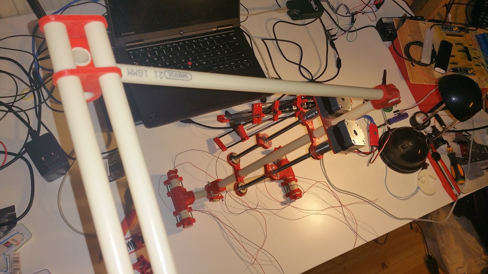
Here is a picture of my test setup, because i know you want to see it ;)

Also a comparison to prior work by me, here i use two NEMA 17 stepper motors with trapezoidal screws. The construction is heavy as hell, i think one Nema 17 stepper weighs significantly more then my entire SEA.

And here are two images of the old linear system on a "test leg".

I have no video of the new design as i managed to get a ESC with SimonK one direction firmware.
It gets boring very fast to manually reverse the rod and then drive it and then manually reverse it again.. So of cause i want to be able to actuate the motor in both directions so next entry on this blog will cover how to re-flash a SimonK ESC and i might also poke around in the FW a bit.
Todo:
- Re-flash ESC
- Make fancy video
- Add sensors to SEA
- Upload design files to github
- Make a Spring simulator
- Make a Spring generator
As always any contribution, comments and discussions are welcome!
Lets build something great together.
Part 3 is now available here.
Saturday, December 17, 2016
Building a low cost, light weight, closed loop, Series Elastic Actuator (SEA)
Now you might ask, what is a SEA, its kind of a servo with dampening.

When you build a robot, you probably want to be able to detect impacts or get the load on a specific joint or actuator and you do not want it to break on high impacts. Here is where a SEA gets handy.
A better description can be found in the conclusions section of: Matthew M. Williamson's paper "Series Elastic Actuator"
"Conventional robotic actuators suff er from a number of problems when it comes to
providing good torque control. A way to address this problem has been presented
in this thesis. If an elastic element is placed in series with the output of an electric
motor, the force control performance of the motor is improved. The motor is isolated
from shock loads, and the e ffects of backlash, torque ripple and friction are filtered
by the elastic element. A further advantage is that the actuator exhibits stable behaviour while in contact with all environments, a quality which has been hard to attain with a conventional
electric motor based actuators. Along with the bene ts of elasticity come disadvan-
tages which include a limit on the maximum force that the actuator can output due
to the mechanical properties of the elastic element, a reduction in the force control
bandwidth due to the low pass nature of the spring, and increased complexity and
bulk in the mechanical design."
In other words, its awesome, with the drawback that it becomes a bit more complex to keep track of the forces applied on your actuator/robot state. But the benefit is significantly lower power consumption as you can store energy in the springs.

An example of an SEA from MIT
With "soft joints" you can almost make the robot walk by it self as seen in this video (passive dynamic walker):
More detailed description on how a SEA works can be seen here:
And finally a very good motivation for using SEA in a walking biped:
To conclude, If you want to build a cheap biped, then you want lower motor power requirements. To achieve that you build it light and you preferably use a SEA.
Next post will show some different designs of a lightweight 3d printable SEA, I will also make the designs, drivers and BOM available on github.
Part 2 is now available here
Thursday, August 11, 2016
An youtube Introduction to biped locomotion
This is a fast review of the basics and history of robotic locomotion.
So what is walking? According to Wikipedia:
“Walking (also known as ambulation) is one of the main gaits of locomotion among legged animals, and is typically slower than running and other gaits. Walking is defined by an 'inverted pendulum' gait in which the body vaults over the stiff limb or limbs with each step. This applies regardless of the number of limbs - even arthropods, with six, eight or more limbs, walk.”
The simplest type of walking is “the compass gait”. Imagine a cart wheel rolling down a slope, now remove the rim and make the wheel roll on the spokes. As long as the spokes are close enough to each other and the slope is steep enough the wheel will "walk" spoke to spoke down the slope.
Instead of using the slope (gravity) to drive the robot you can use a motor (an actuator):
Now we can remove all but two spokes and make them rotate around the axis and we got the compass gait.
Now to make this work in real life we need to tilt a bit side to side in order to avoid hitting the ground when we are trying to swing the leg forward. Here is an real life example:
Now we can replace the slope with actuators:
Back to the un-actuated (no motors) robots, here is a better example (by McGeer) that have knees with gives a very natural walking.
Steve Collin later built a “Passive Dynamic Walker” with a torso and arms:
The work on passive dynamic walkers later inspired the Cornell Walker, the most energy efficient walking robot to date.
More info on the Cornell Ranger can be found here:
But this is sadly not how most robots work, most robots are pre-programmed to follow a specific pattern that do not follow a natural/dynamic flow. They tend to have stiff actuated joints and big feet to keep the balance. Here is a video that shows the most common type of small humanoid robots:
They have very stiff links and joints and are bunching a lot because the force when the foot impact the ground have no damping, this leads to a very power inefficient and unstable walking. They are also very bad at handling uneven terrain.
However it is possible to achieve amazing balance and handle uneven terrain with a stiff robot, here is an example by “Dr. Guero”:
And even more impressive:
Very little is know about the control system other than that it is some kind of learning system “AI” that handles the gait and balance.
So what are the big players doing? Lets first look a bit on some old videos.
One of the most famous biped robots is Honda's Asimo, let's review its history in short:
Lets analyze how Asimo walks (his gait) in this video:
Now i dare you to try to walk like that (imagine that you made no 2 in your pants while walking). Can you make it through a day walking like that? even an hour? your legs will probably start to complain after a few minutes. Its not a very energy efficient or natural gait. Why have Honda made Asimo walk like this?
Asimo and many other robots use a technique that is called Zero Moment Point or ZMP in short. What ZMP states is that if you keep the sum of all horizontal moment forces (vectors) within the area of your feet, you will be stable and won't fall over as easily. If you also keep the hip in the same level and the upper body upright, you will keep the center of gravity between your feet and it will be simpler to balance the robot. This is not the same as saying that it is easy to achieve stable walking with a ZMP based approach.
Here is a video that very illustrates the concept very well.
Notice that the blue cross is in the middle of the robot at all time and that the red cross is within the bounds of the feet at all time. Real humans are tilted slightly forward while walking, We are not statically stable, we can say that while we are walking and running we are constantly avoiding to fall forwards. If we suddenly freeze during walking or running we will face plant the ground.
More info on ZMP can be seen here:
An more natural approach wast taken by “the Leg Laboratory” at MIT. some of the founders of Boston Dynamics have a history from the Leg Laboratory.
So what is the latest and greatest? Many of the older robots that looks awesome and give the impression of being very capable, are not very dynamic. They are often excellent at performing a given task within a specific environment. They walk well in stairs if they start at a given position and the stairs is a certain height and depth. If there is too much deviation from its pre-programmed assumptions it will fail. Today, the research is focused on energy efficiency and dynamic environments. How can we make robots walk on uneven ground? How do we handle unexpected external forces? How do we minimize the power required to walk?
Humanoid robotics have not been a big research subject until after the accident with the fukushima nuclear power plant in 2011. Some of the damage could have been minimized if it had been possible to access the manual valves inside the reactor building. The environment was to harish for a humans and teleoperated robots. An autonomous robot would prove very useful but none such robot existed at the time. In order to accelerate robotic research DARPA had a “Robotics Challange”:
“The DARPA Robotics Challenge (DRC) was a prize competition funded by the US Defense Advanced Research Projects Agency. Held from 2012 to 2015, it aimed to develop semi-autonomous ground robots that could do "complex tasks in dangerous, degraded, human-engineered environments."[1] The DRC followed the DARPA Grand Challenge and DARPA Urban Challenge. It began in October 2012 and was to run for about 33 months with three competitions: a Virtual Robotics Challenge (VRC) that took place in June 2013; and two live hardware challenges, the DRC Trials in December 2013 and the DRC Finals in June 2015”
Here is an video that shows what several teams of researchers and engineers can achieve with 3 years of work:
As you can see there are so many things that can go wrong, the sensors can give false information, actuators can break, control logic can contain bugs, the robot can draw and act on faulty assumptions. The list goes on.
Lets take a look at energy efficiency, energy efficiency is often measured in CoT (Cost of Transport)
CoT = Energy / (weight * distance).
DURUS
CoT ~1.33 (0.23m/s)

Graph from
ATRIAS
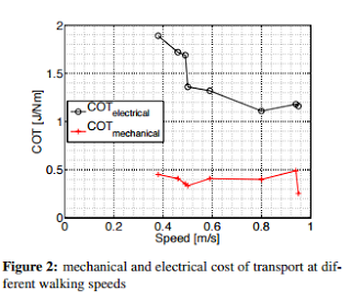
Graph from:
Atlas:
Boston Dynamics seldom release much details regarding their robots.. But here is some coverage:
http://spectrum.ieee.org/automaton/robotics/humanoids/next-generation-of-boston-dynamics-atlas-robot
Here is a table of COT for different machines:
Includes energy to run the motors and all electronics Comparisons:
Vehicle
|
Cost Of Transport
|
Ranger
|
0.28
|
Toyota Prius
|
0.15
|
Human
|
0.2
|
Asimo
|
1.8
|
BigDog
|
15
|
DURUS
|
1.33
|
ATRIAS
|
~1.5
|
The Walk Cycle
When we walk we repeat the same walk cycle over and over with slight deviations to keep our balance and adapt to uneven terrain. We do this without effort unless the terrain gets too uneven and unpredictable, then we have to look down and focus. So basically we have two modes of walking, one “default” that we do without thinking and another where we adapt to the environment and constantly have to focus to not fall over. Here is a image that shows how a “normal” walk cycle works for a human and how ATRIAS and AMBER2 have implemented it.
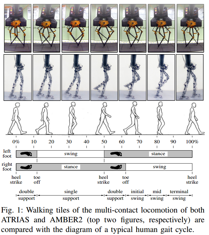
From:
Now to some notes.
Scientific papers are a valuable source of knowledge, you do not have to understand all the mathematical proofs. Many papers contains very informative graphs, tables and state diagrams. Some also link to good youtube videos and github repositories, so do not let a fancy language and a few mathematical formulas scare you away.
More and more publications are also available for everyone for free!
If you want to learn more in-depth course in dynamic walking i highly recommend this free course:
And if you want a introduction to robotics in general you can go through the lectures at http://shanghailectures.org/
They cover many aspects from philosophy, mechanical design to artificial intelligence.
If you, like most, do not use much math in your everyday life. Then you might consider to review your math skills by taking a look at https://www.khanacademy.org/
Here is a few longer lectures/presentations:
NASA Seminar on Bipedal Robots (Aaron Ames, 1h)
Learning to Walk by Actuating a Passive Dynamic Walker (Russ Tedrake) (1h)
Feedback Motion Planning via Sums-of-Squares Verification (Russ Tedrake) (47min)
Jessy Grizzle | Bipedal Walking Robots (37 min)
Sources for additional information:
Amber labs:
Boston Dynamics
Dynamic Robot Laboratory
UT Human Labs
MIT Robot Locomotion Group
https://github.com/RobotLocomotion/drake
Some names to keep track of:
Jessy Grizzle (University of Michigan)
Russ Tedrake ( MIT, Robot Locomotion Group)
Aaron Ames (Georgia Institute of Technology, AMBER labs)
Marc Raibert (MIT, Leg Labs -> Boston Dynamics)
Dictionary:
Actuator
|
Fancy name for thing that move stuff, motor, servo ...
|
Sensor
|
Something that perceives the environment, load cell, webcam, button, accelerometer ...
|
CoT
|
Cost of Transport
|
ZMP
|
Zero Moment Point
|
| Biped | Two legged |
| Gait | walk |
Other Notes:
In real life you will have to deal with things such as mechanical asymmetry, uneven terrain, measurement errors, actuation errors, sensor noise and external forces. The world is a very noisy and chaotic place, and to make a good simulation is a real challenge. But building a walking biped and developing gait control without running any simulations is harder still. You will have to continuously improve both simulation and the real robot.
Please feel free to suggest corrections/ improvements / additions to this article.
// Anton Fosselius
Subscribe to:
Posts (Atom)